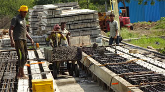
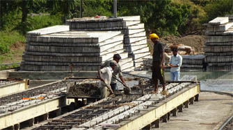
Being a trusted PSC Pole Manufacturer and Supplier, we offer a premium range that is made out of Pre-stressed Concrete for unmatched
strength and durability. Made available in diverse lengths, the PSC Poles are manufactured using advanced techniques under the
supervision of experienced personnel. Moreover, stringent testing is done to ensure the best quality in terms of their strength and
appearance.
| Raw Materials
|
- Cement
- Rod/Wire
- Fine/Coarse Aggregates (Sand & Stones)
|
| Lengths Available |
|
| Finds Application In |
|
PSC pole specification
PRESTRESSED CEMENT CONCRETE POLES ( F.O.S.2.5) FOR 22/11 KV AND LT LINES
(REC SPECIFICATION – 15/1979)
Scope
This Specification covers PSC poles with an overall length of 7.5M.and 9.0M suitable for use in overhead 22/11 KV and L.T. Power lines and double pole structures for 11/0.4 KV substations.
Applicable Standards
Except when they conflict with specific requirements in this Specification, the poles shall comply with the relevant provisions made in the following Indian Standard Specifications:
- IS: 1678-1978, Specification for prestressed concrete poles for overhead power,
traction and telecommunication lines.
- IS: 2905-1966. methods of test for concrete poles for over- head power and
telecommunication lines.
- IS: 7321-1974, Code of practice for selection, handing and erection of concrete
poles for overhead power and telecommunication lines.
Terminology
- For the purpose of this standard, the following definitions shall apply
- Average Permanent Load
That fraction of the working load which may be considered of long duration over a period
of one year.
- Load Factor
The ratio of ultimate transverse load to the transverse load at first crack.
- Transverse
The direction of the line bisecting the angle contained by the conductor at the pole. In the
case of a straight run, this will be normal to the run of the line.
- Transverse Load at First Crack
For design, the transverse load at first crack shall be taken as not less than the value of
the working load,
- Working load
The maximum load in the transverse direction, that is ever likely to occur, including the
wind pressure on the pole. This load is assume to act at a point 600 mm below the top
with the butt end of the pole planted to the required depth as intended in the design.
- Ultimate Failure
The conditions existing when the pole ceases to sustain a load increment owing to either
crushing of concrete, or snapping of the prestressing tend on or permanent stretching of
the steel in any part of the pole.
- Ultimate Transverse Load
The load at which failure occurs when it is applied at a point 600 mm below the top and
perpendicular to the axis of the pole along the transverse direction with the butt and of
the pole planted to he required depth as intended in the design.
Applications
7.5 M and 8.0 M Poles
These poles shall be used at tangent location for 11 KV and L.T. lines in wind pressure zones of 50 kg/M², 75 Kg/ M² and 100 Kg/M² in accordance with REC Construction Standards referred to in the following table.
These poles shall be used for double pole structures of distribution transformer centres as per REC Construction Standards F-1 to F-4 and for special locations in 11 KV and L.T. Lines, such as road crossings etc.
| Pole length |
Line description |
| 8.0M |
11 KV lines with earth wire L.T. lines, vertical formation.
|
| 9.0M |
22 KV lines with earth wire vertical formation. |
MATERIALS
- Cement:
The cement used in the manufacture of priestesses concrete poles shall be ordinary or
rapid hardening Portland cement conforming to IS: 269 – 1976 (Specification for ordinary
and low heat Portland cement) or IS: 8041. E-1978 ( Specification for rapid hardening
Portland cement)
- Aggregates:
Aggregates used for the manufacture of pre-stressed concrete poles shall conform to IS:
383-1970 (Specification for coarse and fine aggregates from natural sources for
concrete). The nominal maximum size of aggregates shall in no case exceed 12mm.
- Water:
Water should be free from chlorides, sulphates, other salts and organic matter. Potable
water will be generally suitable.
- Admixtures:
Admixtures should not contain calcium chloride or other chlorides and salts which are
likely to promote corrosion of pre-stressing steel.
- Pre-stressing Steel
The pre-stressing steel wires, including those used as unmentioned wires should conform to IS:1785( Part-I)-1966 ( Specification for plain hard –drawn steel wire
for prestessed concrete. Part-I cold drawn stress relieved wire), IS:1785(Part-Ii)-1967(
Specification for plain hard-drawn steel wire). or IS:6003-1970 ( Specification for indented
wire for pre-stressed concrete). The type designs given are for plain wires
of 4mm diameter with a guaranteed ultimate strength of 175Kg/mm².
- The concrete mix shall be designed to the requirements laid down for controlled concrete
(also called design mix concrete) in IS:1343 – 1980 (Code of practice for prestressed
concrete) and IS:456-1978 (Code of practice for plain and reinforced concrete), subject
to the following special conditions,
- Minimum works cube strength at 28 days should be at least 420 Kg/cm².
- The concrete strength at transfer should be at least 210Kg/cm².
- The mix should contain at least 380 Kg. of cement per cubic meter of concrete.
- The mix should contain as low a water content as is consistent with adequate
workability. If it becomes necessary to add water to increase the workability, the cement
content also should be raised in such a way that the original value of water cement ratio
is maintained.
Design Requirements
The poles shall be designed for the following requirements.
- The poles shall be planted directly in the ground with a planting depth of 1.5
meters.
- The working load on the poles should correspond to those that are likely to come
on the pole during their service life Designs given are for 140 Kg.
and 200Kg. Applied at 0.6 M from top.
- The factor of safety for all these poles shall not be less than 2.5.
- The average permanent load should be 40% of the working load.
- The F.O.S against first crack load shall be 1.0.
- At average permanent load, permissible tensile stress in concrete shall be 30
Kg/cm².
- At the design value of first crack load, the modulus of rupture shall not exceed
55.2Kg/cm² for M 420 concrete.
- The ultimate moment capacity in the longitudinal direction should be at least one
fourth of that in the transverse direction.
- The maximum compressive stress in concrete at the time of transfer of prestress
should not exceed 0.6 times the cube strength.
- The concrete strength at transfer shall not be less than half the 28 days strength
ensured in the design.i.e.420x 0.5= 210 Kg/cm².
For model check calculations on the design of poles, a
reference may be made to the 3 REC ”Manual of Manufacturing of solid PCC
poles, Part- I - Design Aspects”
Dimensions and Reinforcements
The cross – sectional dimensions and the details of pore stressing wire should conform
to the particulars.
The Provisions of holes for fixing cross-arms and other fixtures should conform to the
REC standards referred to in clause 4 of this specification and in accordance with the
construction practices adopted by the State Electricity Boards.